HybridDiskEncoder
Hybrid Disk Encoder
https://github.com/JamesNewton/HybridDiskEncoder Home of this project
This encoder is based on the Haddington Dynamic Analog / Digital Hybrid encoders used on the Dexter robot arm:
https://github.com/HaddingtonDynamics/Dexter/wiki/Encoders
Please take a moment to read and understand that revolutionary system before continuing here; many of the goals of this project won’t
make sense with out understanding it.
A key point is the “eye” graph shown on that page which seems to confuse people. Here is a step by step set of questions which may help:
-
A standard quadrature encoder has two sensors, 90 degrees out of phase, right?
-
Also 90 degrees out of phase: Sine and Cosine, right?
-
Look up “plot sine on x and cosine on y” and see what picture you get… it’s a circle right?
-
But what is the center of the circle? zero on the standard graph, but the A2D encoder chips don’t give you + - through zero, they go from e.g. 0 to 8192 right? So the center of the eye would then be around 4096… So you have to subtract some from each to recenter it. And that is the center point of the eye.
-
And the analog electronics don’t always go from 0 to 8192… sometimes they are e.g. 123 to 7994 or like that. So… what if they are only 123 to 5678? “Zero” isn’t at 4096 anymore. It’s at the average of those two.
-
Doing this “Eye calibration” simply finds the true center so atan2 returns correct angles despite offsets/imperfections.
Physical Design
Laser cut: Instead of using 3D printed disks, this project will focus on laser cut parts or PCBs. As laser cutters become more available and lower cost, their greater resolution and the simplicity of not supporting 3 dimisional objects may provide a cleaner signal and easy processing. PCBs can be milled with excellent precision and are very strong, opaque, and can support silk screen as well as through-slots.
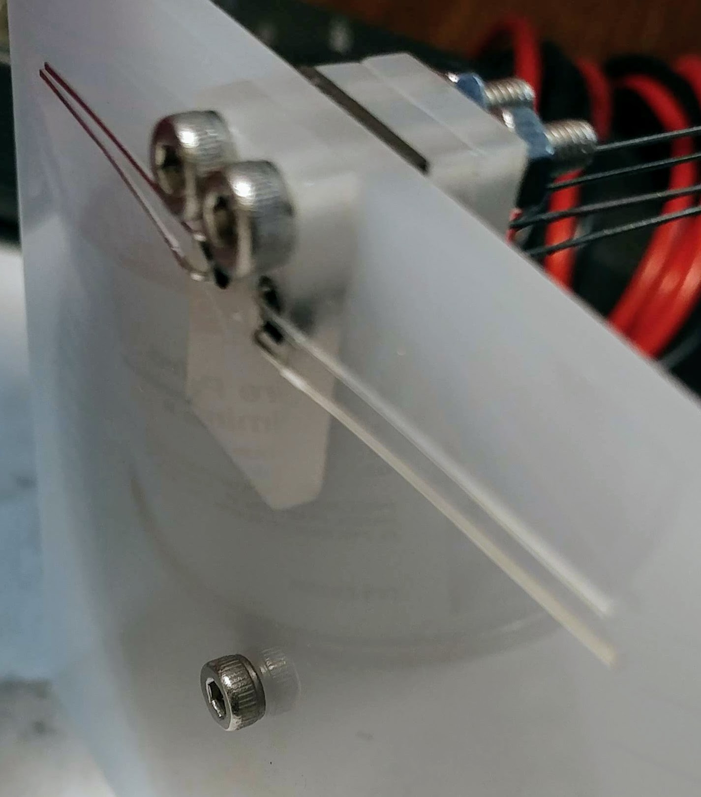
Test Jig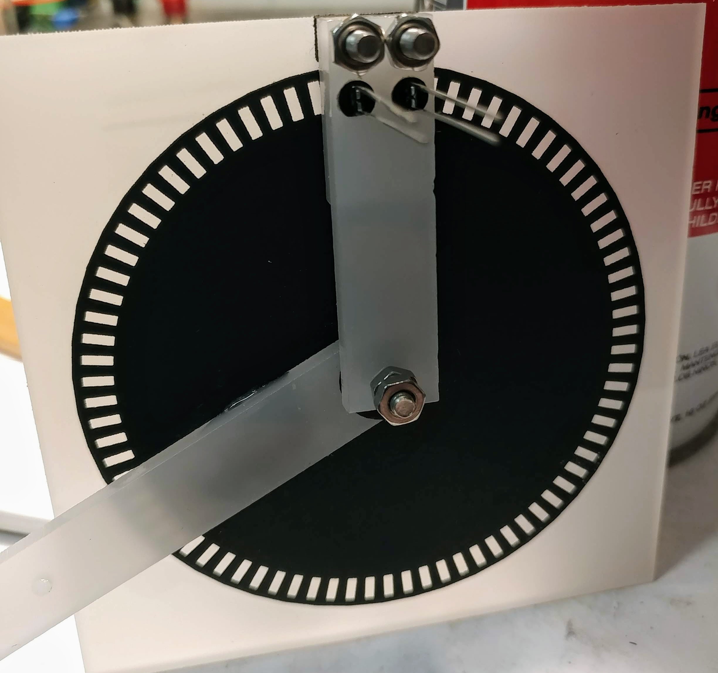
|
|
Layers
Encoder center hub layers:
- base,
- stgc washer,
- opaque disk support and code disk,
- moving arm,
- washer,
- top support arm.
At edge:
- emitter mount, (below base)
- base w/ holes for M3 screws and emitters,
- riser x2,
- opaque mask, in the correct shape
- detector mount,
- top support arm (w/holes for detectors).
OpenJSCAD: In keeping with the focus on Javascript in DDE (the Dexter IDE), node.js processing for remote control, and an upcoming
Robotics class, this project uses
https://OpenJSCAD.com
as the CAD system of choice. This is unusual and may deter collaboration (hopefully not) but if you look at the code for a while,
it becomes obvious that it just isn’t that different from a regular cad system. The CAD system can be viewed and played with
by going to OpenJSCAD.com first, then copy in any of the .jscad files contents from above, e.g. the
stgc_wheel.jscad
Use the mouse to turn the model (shift to shift, ctrl or scroll to zoom), scroll through the code on the right,
and edit parameters in the control block lower left. Switch from “Assembly” to “Parts” (bottom control block) to generate DXF or SVG
output for cutting.
Electronics
Super simple.
- PWM outputs through 15k resistors to 220uF ground filter caps to LTE-4206 940nm IR emitters. A DAC would probably be better.
- ADC inputs from 1M trim pots (Bourn 3386 105) as votage divider to ground with center tap to LTR-4206E to +3.3V rail.
A tinkercad circuit showing the layout on the breadboard is available at: https://www.tinkercad.com/things/1E6iSQBTIGK-hybrid-encoder
Processor
FPGA? The original encoder used a MicroZed with Zinq 7020 FPGA. Let’s see if we can get the cost down a bit? Because the primary goal of this project is to enable a very low cost encoder, it will not depend on FPGA speed. One application is for a human input device, and as humans don’t move that fast, and have builtin motion control systems that avoid the need for a high speed feedback loop. When used as an encoder for robotics, rapid motion can be supported by switching to digital reading of the quadrature sensors, or via an inner single track grey code.
For now, the standard C/C++ math.h atan2 is fast enough, but if we feel the need for speed:
- Interesting discussion of ultra ATAN2 methods: https://web.archive.org/web/20180529001306/https://www.coranac.com/documents/arctangent/
- http://f3.to/portfolio/math/fastatan2.htm Fast atan2.
if |X|>|Y| [(-b*x*y)/(x^2+ a*y^2) + c*sign(x)] else [-c*sign(x*y)= c*sign(x) + (b*x*y)/(y^2+a*x^2)] where a = 0.28088, b = 180/Pi, c = b/2*Pi
PSoC4? Previously, we focused on the
Cypress PSoC 4 chips
for the processor.
http://www.cypress.com/part/cy8c4247azi-m485
It is featured in this development system:
http://www.cypress.com/documentation/development-kitsboards/cy8ckit-043-psoc-4-m-series-prototyping-kit $10 WITH a debugger!
This gives us:
- 8 channel, 12 bit ADC 1-Msps,
- programmable analog front end (no need for external opamps),
- PWM output to adjust emmiter brightness (no need for manual adjust),
- 128K FLASH, 16K RAM, 48 Mhz, 32 bit ARM Cortex-M0.
However,
- it can NOT be run under wine
https://appdb.winehq.org/objectManager.php?sClass=application&iId=16168 - And the need for a frontend is removed by a little digital filtering and using PWM to control the brightness of the LEDs.
The original PSoC Firmware is in the “Firmware” folder
PiPico! Happily, it turns out the PiPico is perfectly capable. The A2D is less able, but for a first version, it’s perfectly able, and less complex. It’s easy to program via Wokwi.com or Arduino IDE via the Earle Philhower board support files. See the HybridEncoder.ino file in the home directory. Hint: these labels are very handy.
Building the Firmware
IDE: Just the current Arduino IDE the Earle Philhower board support files or https://wokwi.com/
With this code, we can see the sin, cos, and computed atan2 which gives us about 1000 clicks inside each slot! Again, the point is that this divides up each slot, and then we can count (already done) the slot which multiplies the clicks. With 1000 per slot and 126 slots, that is 126,000 CPR. Note the lack of smooth motion here is due to sticktion in the very poor bearing (there isn’t one) in the test rig. The actual joint will be smoother.
Single Track Grey Code
The analog reading of our position in a single slot is an “absolute” position, not relative (like a standard quadrature encoder). With Single Track Grey Codes we can provide an absolute position to a single slot. There is a second disk “hidden” under the main disk which has a STGC pattern cut in it, and the base of the test rig has slots for the sensors. The STGC Explorer shows the know working codes, helps to validate possible new codes, visualizes the sequence and sensor position, and then produces the C code to decode the readings. See issue 5 for the current status.
Questions:
Detector to support mount should be adjustable? Or will laser cut and assembly be accurate enough?
Status:
- Done: CAD encoder, (some disks have been lasercut and appear to work well.)
- Done: Order parts for electronics
- Done: Order thin (1 or 2mm) acrylic and black / opaque cardstock. 110lb Cardstock with 3mm Acrylic seems to work
- Done: Lasercut parts for test assembly, update CAD as needed
- Done: Write test firmware for PWM control of the LEDs and A2D feedback to PC.
- Done: Connect LEDs / Sensors to dev board, test and update design
- Done: Set the PWM levels on the LEDs to get full range response on the A2D
- Done: Calculate ATAN2 on board and return degrees.
- Done: Count slots (standard quadrature decode) and combine with ATAN2 degrees #8
- Done: Open shaft passthrough #6
- TODO: Add support for Single Track Grey Code absolute position. See #5
- TODO: Add DDE4 support for serials connected devices
- TODO: Produce and assemble a joint with shaft pass through, integrated (on joint) encoder, separate(able) drive box for different motor sizes / types. #9
See also:
- https://photos.app.goo.gl/v6FCJX8Efcgw1NGY7 photo album of ongoing work.