
Training embedded apps to process speech may be as easy as finding the right 8-bit micro. Don't let what Rodger has to say about using an ADPCM algorithm and PWM output to generate speech to go in one ear and out the other.
The ultimate form of feedback from a product is through speech. A product that reacts to stimuli with a verbal response is more likely to grab your attention than one without the capability.
In most cases, adding speech recording and playback requires extra processor bandwidth or an additional device such as a DSP or specialized audio processor. The cost, complexity, or lack of additional bandwidth, however, can prevent the speech features from being integrated into the product.
Now, if the words "8-bit microcontroller" were mentioned with respect to speech, some might chuckle to themselves, others might break into a fit of uncontrollable laughter, but certainly all would read on. Yes, it’s true: A simplified Adaptive Differential Pulse Code Modulation (ADPCM) algorithm can be implemented on a low-cost 8-bit micro.
In this article I explain the tradeoffs between bit rate and quality that are important in determining if you can use an 8-bit controller in the product. I also present the details of the origin as well as features of the ADPCM algorithm. Finally, I cover methods of integrating the microcontroller into the application as a speech encoder/decoder peripheral or as a complete speech-processing subsystem.
When choosing a speech processor, you must first determine the desired quality of the speech reproduction. A speech-processing system attempts to balance the quality of the reconstructed speech with the bit rate of the encoding/decoding. In most cases, speech quality degrades as the bit rate drops.
The search for a happy medium between bit rate and quality has filled volumes. A high bit rate, high-quality speech processor implies a sophisticated algorithm that is computationally intensive with long encoding/decoding delays (i.e., requires the use of a DSP or special audio processor device).
This would also imply that an 8-bit microcontroller is not a solution for all applications but can provide reasonably good quality at medium-to-low bit rates. These tradeoffs between bit rate, quality, and the complexity of the system can be summarized by the following questions:
• What level of speech degradation can be tolerated?• What is the highest bit rate a system can tolerate (in terms of bandwidth)?
• What are the limitations on operating frequency, printed circuit board area, and power consumption?
• How much can you afford to spend on the speech subsystem?
Unfortunately, one answer can’t satisfy all these questions. However, cost seems to drive most decisions.
Cost is the main factor behind bit rate. Lower bit rates are desirable because they lower operating bandwidth as well as memory storage requirements. It also means less memory to store, a fixed amount of speech, and lower cost. Figure 1 shows graph of speech quality versus bit rate.
Figure 1—A designer must make tradeoffs between bit rate and quality of reconstructed speech. After defining these two parameters, the selection of a speech coding algorithm can be made. |
A typical system might sample speech with a 12-bit ADC at a rate of 8 kHz, which is more than sufficient to preserve signal quality. At this rate (i.e., 96 kbps), 1 min. of storage requires 720 KB.
To transmit the information over a communications channel requires something higher than 96 kbps to permit supplemental information (e.g., start-of-frame indicators, channel number). These requirements are beyond the scope of most applications and can be reduced by using speech coding.
Speech-coding techniques for reducing the bit rate fall into two categories. The first method is called waveform coding.
There is a higher probability of a speech signal taking a small value rather than a large value. So, a speech processor can reduce the bit rate by quantizing the smaller samples with finer step sizes and the large samples with coarse step sizes.
The bit rate can be reduced further by using an inherent characteristic of speech—there is a high correlation between consecutive speech samples. Rather than encode the speech signal itself, the difference between consecutive samples can be encoded. This relatively simple method is repeated on each sample with little overhead from one sample to the next. An example of a waveform algorithm is ADPCM.
The other way to reduce bit rate is to analyze the speech signal according to a model of the vocal tract. The speech remains relatively constant over short intervals and a set of parameters (e.g., pitch and amplitude) can define that interval of speech. These parameters are then stored or transferred over the communication channel.
This technique requires significant processing on the incoming signal as well as memory to store and analyze the speech interval. Examples of this type of processor (called a vocoder or hybrid coder) are linear predictive coding (LPC) or code-excited linear predictive coding (CELP).
Quality is difficult to define or even measure. The goal of a measurement is to completely describe the quality of a speech processor in a single number. This measurement should be reliable across all measurement platforms as well as speech algorithms.
Unfortunately, however, measurements are broken up into subjective and objective. Subjective tests measure how a listener perceives the speech. Objective tests compare the original speech against the reconstructed output and make measurements based on signal-to-noise ratio (SNR).
The goal of a subjective test is to represent the personal opinions of a listener about the reconstructed speech in a single number. The listener evaluates speech segments based on the intelligibility or signal degradations (e.g., nasal, muffled, hissing, buzzing, and so forth. Several subjective tests exist such as diagnostic rhyme test (DRT), mean opinion score (MOS), and diagnostic acceptability measure. Table 1 shows the MOS score and bit rate for some common speech processors.
| Coder name | Algorithm type | Bit rate | MOS |
| G.711 | log PCM | 64 | 4.3 |
| G.721 | ADPCM | 32 | 4.1 |
| G.723 | CELP | 5.6 & 6.4 | 3.9 |
| G.726 | ADPCM | 16, 24, 32, 40 | –, 3.7, 3.9, 3.9 |
| G.727 | ADPCM | 16, 24, 32, 40 | –, 3.7, 3.9, 3.9 |
| G.728 | Low delay CELP | 16 | 4.0 |
| FS 1015 | LPC-10 | 2.4 | 2.3 |
| FS 1016 | CELP/MELP | 4.8/3.2 | 2.4/3.5 |
| GSM | RPE-LTP | 13 | 3.5 |
| — | MBE | 4.8 | 3.7 |
Table 1—To help reduce the decision-making process, designers should rely on speech coder test results such as MOS, DAM, or SNR. Typically, the lower bit rate algorithms are significantly more complex than the higher bit rate ones.
As I said, objective testing usually involves SNR measurements. SNR is a measurement of how closely the reconstructed speech follows the original signal. The speech signal is broken up into smaller segments, and the SNR is measured. All the SNR measurements are averaged together to get an overall SNR measurement for the speech signal.
Although this measurement is sensitive to variations in gain and delay, it cannot account for the properties of the human ear. The input to the speech processor is usually a sine wave or narrow-band noise waveform to maintain a repeatable test for all systems.
Because determining the quality of the speech processor is not as easy as picking the best number, both kinds of tests should be used to identify the best processor for your application. The best method may be to sit and listen to the outputs of the speech processor and simply select the one that you like the best. After all, quality is not a measured parameter but rather a listener-perceived parameter.
ADPCM is a waveform coding technique that attempts to code signals without any knowledge about how the signal was created. This implies that a waveform coder can be applied to other forms of data besides speech (e.g., video). In general, these coders are simple, with bit rates above 16 kbps. Anything lower degrades the reconstructed speech.
ADPCM is based on two principles of speech. Because there is a high correlation between consecutive speech samples, a relatively simple algorithm could be used to predict what the next sample might be, based on previous samples.
When the predicted sample was compared to the real sample, it was found that the resulting error signal had a lower variance than the original speech samples and could therefore be quantized with fewer bits. It was also found that no side information about the predictor would have to be sent if the prediction was based on the quantized samples rather than on the incoming speech signal.
The result was differential pulse code modulation, formerly named ITU-T G.721. Further studies showed that if the predictor and quantizer were made to be adaptive (i.e., that smaller samples are quantized using smaller steps and larger samples with larger steps), then the reconstructed speech more closely matched the original speech.
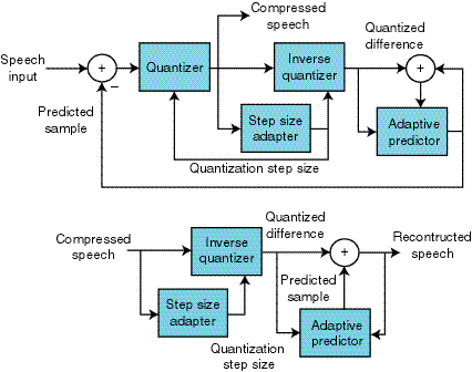
This adaptation helps the speech processor handle changes in the incoming speech signal more effectively. Thus the creation of ADPCM standardized to be ITU-T G.726 and G.727. Figure 2 shows a block diagram of the encoder and decoder portions of ADPCM. Notice that both the encoder and decoder share the same quantizer and predictor.

Figure 2—Because the decoder block is embedded in the encoder, the ADPCM algoritm does not need to send or store any additional side information with the compressed data. |
Most DSP manufacturers can show some type of speech algorithm that has been implemented for their architecture. Very few 8-bit microcontroller manufacturers can say the same due to the horsepower required to implement the speech coding algorithms.
The ADPCM algorithm discussed in this article was developed by the now defunct Interactive Multimedia Association (IMA) based on an Intel DVI variation of the standard G.726. Normally, this algorithm is quite rigorous in the computation category, but the IMA version reduces the floating-point math and complex mathematical functions to simple arithmetic and table lookups.
A 16-bit 2’s complement speech sample is converted into a 4-bit ADPCM code. The algorithm uses approximately 600 words of program memory and 13 bytes of data memory. Almost any 8-bit microcontroller can implement this algorithm thanks to the small amount of resources required.
The source code gives the complete ADPCM encode and decode routines written for use in Microchip’s assembler (MPASM). The missing piece to the source code is that for each message recorded or played, all the registers (PrevSampleL, PrevSampleH, and PrevIndex) must be cleared.
A simple encoder/decoder peripheral can be implemented around a PIC12C672 or a PIC16C556A. The first thing to consider is the communication interface between the PIC and the main processor.
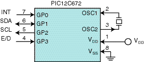
Lower end micros don’t have any type of serial or parallel peripherals but they can be easily implemented in firmware. The complete code shows routines that can perform I2C, SPI, and RS-232 communications with a host processor, and Figure 3 shows a block diagram for an I2C implementation on a PIC12C672.

Figure 3—The PIC12C672 provides the smallest solution for a serial coder peripheral. In addition to the I2C signals SDA and SCL, this device features an interrupt and encode/decode select signals. |
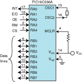
Because the microcontroller is implementing the serial interface in firmware, the application must ensure a good handshaking method to keep the micro from overflowing. A parallel interface routine is much easier to develop than the serial protocols, and Figure 4 shows an example of the parallel interface to a PIC16C556A.

Figure 4—The PIC 16C556A provides a cost-effective parallel-interface solution to a speech coder peripheral. In addition to the standard parallel interface signals, it provides an interrupt and encode/decode select signals. |
The master I2C routine uses approximately 77 words of program memory and 5 bytes of data memory. MPASM must also be used to assemble this file.
One consideration when designing a system based around this routine is the transfer rate. If the PIC is the master of the interface, then the transfer rate is solely determined by the clock source to the microcontroller. If the PIC is a slave on the interface, then the transfer rate depends on the clock source as well as the firmware overhead to sample the incoming data.
The SPI slave routine uses approximately 16 words of program memory and 2 bytes of data memory. The same consideration concerning clock rate applies to this routine as well. Because of the overhead of sampling the SDI pin, the maximum clock frequency for SPI slave is at least 18 instruction cycles, where one instruction cycle is the oscillator frequency divided by four.
The RS-232 routine uses approximately 54 words of program memory and 3 bytes of data memory. Although you should check to make sure that the micro has plenty of overhead, the transfer rate of RS-232 is usually much less than the PIC’s oscillator frequency.
This routine only requires the user to define the oscillator frequency and the transfer rate. Several equations allow MPASM to calculate the necessary delays for bit times.
After the communication protocol is chosen, you have to put all the pieces together. First you need to implement some type of data request from the main processor to the micro (for master) or from the PIC to the main processor (for slave).
The micro must control the flow of data to/from the main processor because the communication interface is implemented in firmware and not hardware. Otherwise, data may be lost. For a slave implementation, a single I/O line from the PIC connected to an external interrupt pin on the host processor easily accomplishes this.
The other important piece of information is the type of operation to be performed: encode or decode. This step can be accomplished two ways. First, a unique command from the host processor to the microcontroller can set the operation to follow. The host processor then initiates an encode or decode sequence by sending the command for encode or decode.
For an encode sequence, the host processor sends two 16-bit, 2’s complement samples to the PIC. The PIC then responds with two 4-bit ADPCM codes packed into one byte. A decode sequence reverses the order. One byte of ADPCM codes are sent to the PIC, which responds with two 16-bit, 2’s complement samples.
The second method is to use an I/O line from the host to the PIC to indicate an encode operation (I/O pin pulled low) or a decode operation (I/O pin pulled high). Note that encode and decode operations should not be mixed together.
All of the data to encode or decode should be sent consecutively to the micro. Once all of the data has been processed, the host processor can change the type of operation to be performed.
This requirement is due to the fact that the ADPCM algorithm processes the next data based on previous data. Anytime the operation is switched, the encoder or decoder is initialized to a cleared state.
One other consideration is the selection of clock source to drive the PIC. The PIC’s oscillator structure is flexible so either an external clock from the host processor or a local oscillator can be connected to it.
If your application has one system clock that drives all devices on the board, this same signal can be driven into the oscillator input on the PIC. Otherwise, a standard oscillator circuit can be used to provide the clock signal.
You can also use a PICmicro as a complete speech-processing subsystem. The PIC16C77x devices are an ideal choice for this because of the 12-bit ADC and 10-bit PWM peripherals. The new PIC18Cxxx, can implement stereo record and playback at an 8-kHz sample rate because of the optimized instruction set, architecture, and 40-MHz operation.
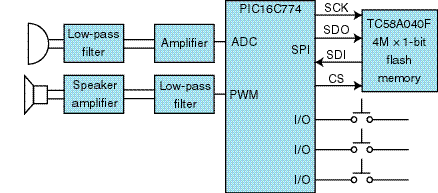
The PIC can communicate to the host processor via any serial interface or even a simple keypad that implements play, record, next message, and previous message. Figure 5 shows a simplified block diagram of the speech subsystem based on a PIC16C77x device.

Figure 5—For those applications requiring a complete speech-processing subsystem, the PIC16C774 with integrated 12-bit ADC, SPI, and 10-bit PWM provides the most integrated solution. |
The microphone input must be both filtered and amplified before entering the microcontroller. This input might be designed in two stages.
First, an amplifier stage with some limited automatic gain control provides somewhere between 40 and 60 dB of gain. The filter stage might be a fourth-order filter centered at 4 kHz for an 8-kHz sample rate. The PIC samples the incoming signal at 8 kHz and compresses the 12-bit sample down to four bits.
The memory size is determined by the amount of record time desired. At 8 kHz, the system requires 4 kbps of storage (8000 samples/s × 4 bits/sample). Therefore, 1 min. of record time requires 240 KB.
An ideal match for this type of system is the Toshiba TC58A040F 4M × 1 NAND flash-memory device. It stores approximately 131 s of speech at an 8-kHz sample rate and uses SPI as the communications interface.
You now have a choice to make on the speech output circuit. Although a DAC makes sense in some applications, the PIC’s onboard 10-bit PWM peripheral can also be used to lower cost without giving up quality.
Admittedly, the DAC has better quality than the PWM, but with the right filtering, the PWM module can provide good results. This filter can be a fourth-order filter centered at 4 kHz (and can be a copy of the input filter).
The final circuit—the speaker amplifier— is extremely application dependent. You may want to drive a speaker or a set of headphones. Many companies, including National Semiconductor and TI, make amplifiers specifically for driving speakers or headphones.
Although some applications need the high bit rate and high-quality speech algorithms, most can use one like mine. Don’t underestimate the power of the 8-bit microcontroller. Given the right device, the medium bit-rate algorithms can be implemented successfully without a DSP or specialized audio device.
Improvements to the 8-bit architecture, operating speed, instruction set, and memory sizes that have allowed the migration of low-end DSP applications to the 8-bit world. If you’ve never used a PWM module to generate speech, try it. You might be surprised.
Rodger Richey has worked for Microchip for more than four years in principal engineer and senior applications engineer positions. You may reach him at rodger.richey@microchip.com.
SOFTWARE
The software for this article available here.
[1] N.S. Jayant and P. Noll, Digital Coding of Waveforms, Principles and Applications to Speech and Video, Prentice Hall, Englewood Cliffs, NJ, 1984.
[2] P.E. Papamichalis, Practical Approaches to Speech Coding, Prentice Hall, Englewood Cliffs, NJ, 1987.
[3] IMA Compatibility Project, Recommended Practices for Enhancing Digital Audio Compatibility in Multimedia Systems, V.3.00, Oct. 1992.
[4] R. Richey, Adaptive Differential Pulse Code Modulation using PIC16/17 Microcontrollers, AN643, Embedded Control Handbook, Microchip Technology, 1996.
[5] J.D. Tardelli, E.W. Kreamer, P.A. La Follette, and P.D. Gatewood, A Systematic Investigation of the Mean Opinion Score (MOS) and the Diagnostic Acceptability Measure (DAM) for Use in the Selection of Digital Speech Compression Algorithms, ARCON, www.arcon.com/dsl/sl24a.html.
Comp.speech FAQ, www.speech.cs.cmu.edu/comp.speech
Dynastat Inc., Subjective Testing and Evaluation of Voice Communications Systems, www.bga.com/dynastat/index.html
T. Robinson, Speech Analysis, Cambridge University Engineering Dept., Speech Vision Robotics Group, www-svr.eng.cam.ac.uk/~ajr/SA95/SpeechAnalysis/SpeechAnalysis.html
J. Woodard, Speech Coding, Dept. of Electronics and Computer Science, University of Southampton, rice.ecs.soton.ac.uk/speech_codecs/index.html
PIC12C672, ’16C556A,
’16C774
Microchip Technology, Inc.
(480) 786-7200
Fax: (480) 899-9210
www.microchip.com
Amplifiers
National Semiconductor
(800) 272-9959
(408) 721-5000
Fax: (408) 739-9803
www.national.com
Texas Instruments, Inc.
(508) 236-3800
www.ti.com
© Circuit Cellar, The Magazine for Computer Applications. Reprinted with permission. For subscription information call (860) 875-2199, email subscribe@circuitcellar.com or on our web site at www.circuitcellar.com.
Questions:
Comments:
| file: /Techref/com/circuitcellar/www/http/pastissues/articles/richey110/text.htm, 26KB, , updated: 2008/2/11 16:47, local time: 2025/10/18 10:36,
216.73.216.53,10-2-207-162:LOG IN
|
| ©2025 These pages are served without commercial sponsorship. (No popup ads, etc...).Bandwidth abuse increases hosting cost forcing sponsorship or shutdown. This server aggressively defends against automated copying for any reason including offline viewing, duplication, etc... Please respect this requirement and DO NOT RIP THIS SITE. Questions? <A HREF="http://massmind.org/Techref/com/circuitcellar/www/http/pastissues/articles/richey110/text.htm"> richey110</A> |
| Did you find what you needed? |
Welcome to massmind.org! |
|
Ashley Roll has put together a really nice little unit here. Leave off the MAX232 and keep these handy for the few times you need true RS232! |
.