From Peter plp at actcom,c0,il
It is suitable for low power systems (but there is no rule against using the outputs to drive low at full (20mA) current from another power supply within +/-0.3v+0.6v of the voltage on the decoupling cap).
The bulk diodes {ed: aka the protection diodes inside the PIC} are used during startup, then code turns on the relevant high side output FET {ed: again, this is the output pin driver in the PIC} which conducts both ways, so it can be used for charging and/or extra power (as a low power scheme). Pulsed charging can achieve very low current charging of the backup battery(es).

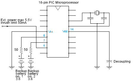
The circuit as shown powers the pic from either battery or the dc input, without the code doing anything. When the code wakes up it should turn on the high side fet where the power comes in and then pulse the high side fets of the batteries to charge them. It cannot really measure the voltage but it can make sure that the integrated current does not exceed the trickle charge current of the NiCd or supercap used.
When external dc drops the pic can detect this (for example by not keeping the high side fet on on the dc input pin, but pulsing it off every few msec) and turn the high side fet off.
The idea is to use two coin cells so they can be changed one by one wihout losing data. Of course you would not charge the coin cells. If using a proper supercap or battery then just one is enough.
I have used such a scheme in a hours meter. It could also work in other systems, like alarms, dongles and clocks.
The inrush limit applies as absolute maximum and is to prevent the Vdd side bulk diode (actually the high side fet) in the pic on pin 8 from destruction if the external source has low impedance and the decoupling capacitor has a low esr. This was not a problem in my case, as power was applied through a large resistor and a parallel regulator (zener) and decoupling.
Xiaofan says:
I think the circuit will be easier to understand if the names of the pins and the internal structure of the PIC port pins are in the picture.I am not so sure if I understand the circuit correctly but I will give it a try.
The one connected to the decompling capacitor (pin14) is the Vdd pin. Normally it is connected to the supply, but not in this case. Port pins have diode protection to Vdd and Vss.
Therefore the external power (5.5V and limit at 50mA) will charge the Vdd decoupling capacitor through the port protection diode to about 5.5V-0.6V=4.9V.
This will make the PIC happy and running. Pin 8 then will be configured as an output pin and output high (to turn the high sider FET on).
Now we can pulse-charge the two backup batteries or supercaps by configuring pin6/pin7 as output pins and outputing high to charge and configuring as input to stop charging.
To detect DC voltage on Pin 8, we need to configure it as an input pin from time to time (thus turn the high side FET off). Once it reads low, we know that the DC voltage drops quite a lot and we'd better turn off the high side FET totally. In this case, the backup batterie(s)/supercap will take over.
Since pin 8 should not sink more than 25mA, the total current consumption should be less than this. The voltage should not be higher than maximum allowed input voltage (Vdd+0.3V). That is why the external DC voltage to pin 8 is typically 5.5V and can drive 25mA at most.
I think this is quite non-standard. ;-)
| file: /Techref/microchip/qndbatbak.htm, 4KB, , updated: 2005/10/12 15:08, local time: 2025/10/17 15:04,
216.73.216.53,10-2-207-162:LOG IN
|
| ©2025 These pages are served without commercial sponsorship. (No popup ads, etc...).Bandwidth abuse increases hosting cost forcing sponsorship or shutdown. This server aggressively defends against automated copying for any reason including offline viewing, duplication, etc... Please respect this requirement and DO NOT RIP THIS SITE. Questions? <A HREF="http://massmind.org/Techref/microchip/qndbatbak.htm"> PIC Specific Battery Backup Power Supply</A> |
| Did you find what you needed? |
Welcome to massmind.org! |
Welcome to massmind.org! |
.