SECTION 1 Hardware Tools
Chapter 1
Introduction
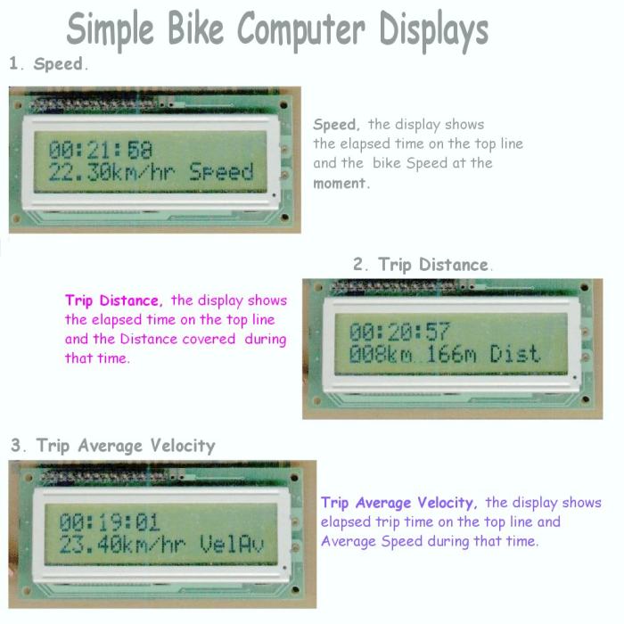
The three displays of the Simple Bike Computer are shown below in fig0 They
switch automatically in the sequence .. Speed… Distance
…AverageSpeed… Speed etc
There are so many embedded controller products in the house these days that
many of us feel we ought to know a little more about how they work. They're
the brains inside things like the washing machine and so many other present
day domestic appliances.
My first personal microchip contact was a friend's radio controlled car which
“died” and was brought to me for repair I being his resident radio
expert.
The opened toy had very little inside, a small receiver, ( it was ok) and
a small chip beside it, controlling the motors to the wheels. The chip was
a PIC. I was out of my depth, best learn how….!!!
The reason for the PIC being there was obvious to me as an engineer. The
printed circuit board was surprisingly empty. That meant the PIC program
was replacing a lot of the traditional circuit's resistors diodes and other
hardware.
I decided I wanted to do something similar . Learn how to program was a priority
in my mind, but not as a theoretical exercise, no, I like to get something
useful at the end of any project.
Bathroom Scales? No, nor a toaster, nor the water heater. They all involved
a lot of hardware, with unfamiliar thermistor sensors. My thoughts turned
to my bike. It had a computer, very small and the sensor input was minimal.
Yes, that was it, a Bike Computer project….. and so it
started.
Our Goal
The bulk of the article that follows is to try and take the mystique
out of the many steps involved in going from an idea to a finished product.
You won't of course be ready to go into full scale industrial production,
but you will now be aware of the things that have to be done, and know how
to do them.
We will look at and master.
Hardware steps
-
Making a PCB from scratch
-
How to use the FREE tools
Software steps
-
-
Very basic Pic source coding
-
Using MPASM
-
Getting the HEX into the PIC
And that is about it. There is NOTHING in the above list that is difficult.
Most of the steps only require time and patience.
WARNING. We
will use no poisonous chemicals , BUT they can BURN HOLES in
you or your clothes.
So when you are making the pcb, PLEASE keep the CHEMICALS away from
the reach of children who are always curious about something
new.
The Master plan
There are many ways to plan a project. But often, the steps we know don't
even figure because they are so obvious….This can cause enormous headaches
for us beginners. So we will try and follow a logical sequence by spelling
out everything that has to be done . There are two big areas to cover, the
hardware and it's construction, then the software and it's application. The
hardware is generally said to be the easiest part of the two so lets start
there.
Note. The current saving techniques such as sleeping the PIC until a wheel
interrupt is detected had to be abandoned when we ran out of memory space.
Even so with the battery 4xAA, this is not a problem for the tests.
Getting the Act together
The initial project outline was supposed to show the major activities and
thus the equipment needed. The “equipment” including physical things
like PCB and program things like the micro and language. The “idea”
diagram is very bare and cryptic, but gets filled in as the project progresses.
So we start with.
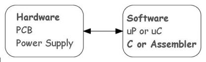
fig1 .Start
It was very clear from the start that ( for me ) the hardware box was easy
to define and make, whereas the software box was full of unknowns. So let's
look at the Software questions.
What is a microcontroller ? and Which microcontroller?
I had found out by then that microcontroller is not just another word for
microprocessor, no indeed. A micro controller is a stand-alone system that
can calculate and connect itself with minimum peripherals directly to the
outside world. The microprocessor also can calculate but needs a lot of
interfacing to get the results to a screen or to a display.
Which microcontroller was harder to get to grips with. After going through
an initial list it became all too clear that the abundant choice was aimed
at experts, it was not for a beginner. That narrowed things down. The PIC
, my first contact, caught my eye time and again, because of the many articles
on offer on the internet and more important, explaining how to make things
with it.
So I read more; specifically about PICs to find the really basic stuff. The
PICLIST was a great starting point, as it talked about activities I had never
even thought about. Especially, how do you test what you are proposing to
make, some sort of simulation was an obvious must. This narrowed the field
down further to things like the 16C84, now slightly obsolete.
Which PIC language?
My searching had uncovered a company called Microchip, which had from the
goodness of it's heart provided a program to check that the code you were
writing was correct. It had a site that offered data sheets on it's products,
and almost all the net sites that talked about PIC's directed you there.
What nobody actually said was which language was better,
ASSEMBLER OR C ( OR C++, OR ???).
As I know a little about C it initially attracted me, but somehow I began
to get the feeling it was an overkill and that the routines were a bit unwieldy.
Also it seemed to be an additional buffer between you and the microcontroller.
During my search someone had commented in an article that correctly written
assembler was very compact and made best use of the “scarce” memory.
So I decided on Assembler. But what was exactly assembler? I thought assembler
code was universal, but it comes in many flavours. PIC assembler is not the
same as that of Intel nor Motorola to cite some of the more important names.,
but PIC was widely used. Not a very logical way to arrive at a conclusion,
but it happened that way.
The Software Shopping List
We now had a starting point and the needed bits and pieces began to become
clear.
-
Find a tutor which explained the PIC
-
Find out how to use MPASM
-
Find out about MPLAB
-
Find out how to get the code into the PIC
The Tutor
There are so many. However one caught my eye as it was big, illustrated and
FREE. After working through it steadily for a couple of days, it pointed
me towards two important areas for getting started.
·To generate the code, you need something to write
it with
·To run the code, you need some program that does
exactly that
After a week of reading the tutor I found I could not put off any longer
doing something about getting a suitable editor and an emulator. They had
to be obtained.
Text Editor
When I'm not writing with a word processor, I use a smaller freeware program
called EditPad . The big word processing programs use a lot of control characters
which the PIC doesn't want, (nor does it know what to do with them).
EditPad light is FREE, and also adds nothing to give the PIC indigestion.
However any small Text Editor designed specifically for writing programs
should be fine.
MicroChip's MPLAB
This is a big big program…. Why chose it ? Well ….
-
It is the recommended PIC maker's program.
-
It has lot's of bolt-on goodies for when we are more advanced or
well-heeled.
-
It can interface, input and output, with other programs,
-
It accepts C as well as assembler or a mix of both
-
It is not too hard to use though telling it what you want to do has to be
exact.
-
It can handle the basic 16C84 as well as it's bigger brothers
-
It is FREE.
The program to get our program into the PIC
The MPLAB after checking that the code written can run error free finally
produces a compiled file with the extension xxxx.HEX.
This .hex file is what the real world PIC needs to get up and running.
But to get the HEX file into the PIC we need a program that can check the
PIC , we need a program that can read the contents of the PIC and write the
code INTO it, burn it.
I personally like a nice little program that does this called ICPROG. The
name I think says it all. It is a program to program your IC, your integrated
circuit, your PIC!!!
It also caters for many different PICs.
ICPROG is easy to use and is , yes you guessed, it is FREE.
Starter Kit
So where can we find all these programs? On the internet of course! If you
search with the names above you will find several sites, some of which will
be the nearest to your location.
If you don't find any of them, then try the list at the end of the chapter
which is hopefully not out of date. These sites will let you download the
needed programs. Try it at night, because some programs are VERY BIG. I'm
referring specifically to MPLAB.
We still have one very important item to add to our shopping list…..the
data sheet for the PIC.
Which one?
Well the 16F84A is a bit bigger memory wise than the original 16C84
and is still not classed as “obsolete. It is limited as far as built
in goodies are concerned.
E.g. you don't get on-board voltage references, nor UARTS nor ADCs, it is
a little slower, but this is good for us learners because it is simpler to
learn with. The bigger chips tend to have so many trees that it gets hard
to see the forest.
To sum up , we need :-
| Item |
Source |
What it does |
| 16F84A data sheet |
Microchip Site and others |
Explains about the PIC |
| Text Editor |
EditPad Site |
For writing no-frills Text |
| MPLAB |
Microchip Site and others |
Test drive your code |
| PIC tutor |
Mikroelektronika |
Tells you How the PIC works |
| ICPROG |
Icprog site |
Stuffs the PIC |
| LCD data sheet 2x16 |
Hitachi 44780 controller |
displays speed, time dist. |
Up to here the total cost is your telephone InterNet
connection
Bill
Once we have these items we can start to get to grips with the bicycle itself.
So let's see what the computer needs to get up and running. We will talk
about the program later.
Defining the Computer
Here I can use a bit of hind-sight and point out things that are to be avoided.
All bike computers have at least one input from a sensor, most will have
this sensor plus a couple of buttons for changing menus. But the essential
part is the sensor which sends a pulse to the PIC.
Sensors
The sensor could be mechanical and every time the bike wheel turns it closes
a switch, or it could be optical and every time the wheel goes round a photocell
detects ( or loses) a light beam.
The mechanical contact on a mud covered mountain bike would be pretty unreliable,
not only because of mud blocking the contacts but the bumps and leaps would
give false readings.
The optical systems are very reliable in general, but not in the mountain
bike situation. A piece of mud covering the detectors eye would happen so
frequently that it would make the detecting system useless.
What's left? Many systems. Just to give an idea of what is possible at the
exotic end, you can carry a GPS terminal. Gives you all the travel data you
want including the names of the place and country you are in, but a bit pricey.
Besides we want to make it ourselves and write the program all at a very
low cost. So is there a low cost reliable sensor?
Well the magnet on the wheel type is almost universal. It is cheap, very
reliable and vibration proof for 20 years or so. ( Theoretically, the bike's
vibration, the flexing of the spokes, all will cause it eventually to demagnetise
itself).
Another thing is that I don't know anyone who has a 5yr old bike computer
as we all tend to buy something more up market or simply get bored with our
present one and buy another.
Getting back to the wheel magnet. It is fixed to a spoke, and usually on
one side of the fork there is a detector. The magnet is aligned to pass this
detector at a distance of not more than 1 to 3 mm every time the wheel rotates.
(Less might be too close as the spoke flexes when the mountain bike lands,
and magnet and detector could become entwined in each other with bad karma
for the bike rider.
The magnetic detector can have many forms. It can be a many turn encapsulated
coil, it can be a HALL EFFECT device proper, or it can be an MR (
magnetoresistive) device, or a Weigand sensor.
But let's stick with the crowd and use a Hall effect sensor. It has a few
drawbacks, but we can always change it later if we want to experiment.
So we want a detector which changes it's output( goes high) every time the
magnetic field gets close, and reverts to its low state when the magnet goes
away. This is usually called a UNIPOLAR Hall effect device.
We want one with all the trimmings, (we don't want to get involved in additional
hardware design). That is , we want a sensor output with the correct level
and good signal conditioning which gives clean, bounce free, and cmos level,
HIGH and LOW states. There are quite a few to choose from. Melexis, Micronas,
Allegro, Siemens… etc etc. So now for our first drawing of the computer
below, + fig.2
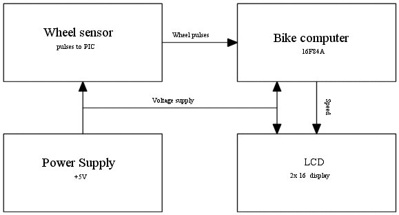
fig. 2
Well fig.2 needs to be padded out a bit with things like what pin goes where,
the connections between pins, and the power supply. To make things easier
for those of us who have never seen a PIC before, lets just look at a
bit of the complete theoretical drawing
to comment the components and functional blocks involved.
Note if 2 wires cross with no dot, they don't touch, if they have a dot where
they cross , then they do touch, i.e., they make contact with each other.
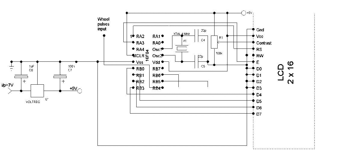
fig.3
On the LEFT we have an integrated circuit ( between the two capacitors) which
needs a minimum i/p of +7V to guarantee a stabilized output voltage of +5V,
On the bike of course this would be a battery.
The next important point is the wire with the legend “Wheel pulse i/p.
On the bike, this is where the sensor sends its output pulses to. Here testing,
we have no bike, instead we generate pulses with another circuit ( a555).
We will talk about the 555 later, it is nothing special, but clutters our
initial view of the Bike computer.
The original project started with a PIC 16F84, but began to run out of memory.
Fortunately it has a big brother, the 16F84A , with the same pin connections
and accepts nearly the same code.
Just to the right of the PIC is the 4MHz xtal oscillator, composed of a 4MHz
xtal and two 22pF capacitors. At such a low frequency the crystal is not
very fussy, providing it is sited near the chip and we have short connections
to the earth plane of the PCB.
Just beside the Xtal block, there is a 100k potentiometer. It adjusts the
contrast of the LCD display. This pot is also non-critical, once adjusted,
you will probably forget about it. So why have a pot there?
The problem is the display contrast. If your display gets fried and needs
to be changed, then it is almost a certainty that you will have to readjust
the pot to get the display contrast back to the “optimum viewing
position”.
In fact my original display would only become visible with a NEGATIVE voltage
applied. Still lets hope there aren't many of those left on the components
suppliers shelves.
The last block is the display itself. There is an LCD standard, a 2 line
by 16 character unit, which is show on top of the introduction on page 1.
The display is the Hitachi type,
( there are many clones), but the important thing is that it has a 44780
controller on board. This is essential as all that follows presupposes that
we are dealing with a 44780 controller to get our information to the
display.
The PIC's 18 pins
Lets look at the previous diagram again, focusing on the various pins of
the PIC.
fig3b
Vss goes to ground and Vdd as well as the reset MCLR to the positive +5V
rail. The osc1 and Osc2 pins were mentioned previously from the point of
view of their physical position. The oscillator itself needs two external
capacitors to function correctly. We have chosen a capacitor value of 22pF
, which should be valid for most xtals. ( Here valid means that the xtal
will see a suitable load and will oscillate correctly). The RA pins and the
RB pins can be used as either input or outputs. The trick is to make the
unused port pins OUTPUTS. Why not inputs? Well this is cmos and you would
be wise to tie them to a reference, probably best, to ground. But then if
you want to use the unused inputs later , this would mean track cutting.
However an unused output can be left free. A reprogram can change it into
an input, with no knife work involved. We mentioned above that there are
RA pins, five of them, for PORTA. Only 2 RA pins are used to connect to the
RS and E pins on the LCD , the other three are programmed as outputs and
are not used. The two RA pins used (PORTA), essentially handshake the data
transfer and indicate we are doing this in the half-byte or nibble mode of
operation of the LCD.
The actual data is sent from PORTB to the LCD. It has to enter the LCD on
pins D7-D4 for the half byte mode of operation. The remaining LCD data input
lines are not used and to be safe, they are tied to earth as we talked about
before. So D0-D3 are connected to ground directly. The data transfer from
the PIC has a restriction, the high nibble always has to be sent first to
the LCD, then the low nibble.
Is that about it? Well almost. The PORTB has 8 pins and any of them could
be programmed as outputs or inputs. But there is another consideration. Later
we will need to use some of these PORTB pins as inputs. Now only pins B4-B7
will give an interrupt signal asking for service. This means that the data
out to the LCD can only be on pins B0-B3.
As an example, the wheel pulse INPUT SIGNAL ( having chosen PORTB), has got
to go to one of the B4-B7 group as an input. It is seen to go to pin B4.
Later we will use the other pins for buttons and LEDS during debugging .
This is an initial hardware justification, not complete but enough for the
moment to enable us to get to the next stage which is mounting the PIC on
a board to be able to program it.
Where to find the Starter Kit
