Parts explanation
of the ultraviolet ray exposure equipment (1)
I make the explanation the following about each part of the ultraviolet ray exposure equipment.
[Menu]>[Manufacturing of Original PCB]>[Implement of the PBC making]>[Ultraviolet ray exposure equipment]>[Equipment explanation]
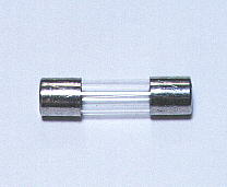
When the circuit short-circuits, it is the one to block off the flow of the electricity.
It is using the one with the 1-ampere current-carrying capacity.
The attenuate fuse line is stored into the glass pipe, and the fuse line melts when the excessive electric current flows and is broken and stops the flow of the electric current.
It doesn't care for the 0.5 amperes.
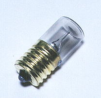 It is the equipment to make the fluorescence light light up automatically.
The bimetal which bends when the heat is added to the pole inside the glow switch is used. Generally, the pole leaves a little and doesn't contact.
The pole in this lamp does the glow discharge when lighting up the fluorescence light.(It shines in the purple)
By this discharge, the pole has the heat. The bimetal bends because of the heat and the pole contacts.
The electric current flows through the filament inside the fluorescence light when the pole contacts. The electron becomes the condition for which it is easy to fly with the heat of the filament.
When the pole contacts, the glow discharge passes away and the bimetal gets cold and returns to the original position and the pole leaves.
When the pole leaves, the electric current is broken and the high voltage occurs to the ballasts in this time. This is to try to hinder the change when the electric current changes in the nature of the coil. ( Lenz's law )
The high voltage which occurred to the ballasts is added to both poles of the fluorescence pipe and the fluorescence pipe begins the shining.
When the fluorescence pipe begins the shining, voltage which is added to the glow switch goes down and there gets not to be a glow discharge.
The glow switch is made to do the glow discharge when the voltage as much as AC100 V is added to the pole.
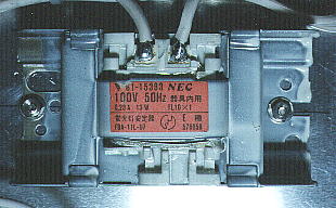
A fluorescent lamp ballast serves two primary functions: it provides the high initial voltage necessary to start the lamp(Refer to the explanation of the glow switch), and it regulates current during lamp operation. The ballast also may provide voltage to heat the lamp's electrodes to assist in lamp starting or lamp operation.
The big electric current becomes the flowing condition when the fluorescence pipe begins to shine. When the big electric current tries to flow through the fluorescence pipe, the ballasts works to prevent it. With this function, the fluorescence light is stable and shines.
The electric current which flows with the wattage of the fluorescence pipe is different. Because it is, it is necessary for the ballasts to have suited the wattage of the fluorescence pipe.
This time, I used one magnetic ballasts(FL10) for the one 10-W fluorescence lamp.
Magnetic ballasts contain a magnetic core of several laminated steel plates wrapped with aluminum or copper windings.
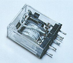
It drives with the timer circuit and it does ON/OFF of the fluorescence light.
Because the timer circuit worked by DC12 V, I use the relay to ON/OFF AC100 V of the fluorescence light.
As for the relay which I used this time, the drive voltage is DC12 V and the specification of the switch part is 240 V and 5 A in case of the AC, and 28 V and 5 A in case of the DC.
This time, it is AC100 V and less than 1 A ON/OFF, it is the one with the enough capacity.
The electric current which flows through the drive coil was to 80 mA be in DC12 V.
I am installing the relay in the socket of the exclusive use.
The other one dosen't care if the drive voltage is DC12 V and the current-carrying capacity of the switch part is the equal to or more than 1 A in AC100 V.