
Also see: other methods if figuring out stepper motor wiring
First, arrange the wires so that there is no way for any of them to be contacting another.
Pick the first wire, tape it and label it "A"
Spin the motor and notice how hard it turns, then connect "A" to one of the other wires, and spin the motor again.
- If you don't feel any difference, put that wire back and try another
- If it feels harder to turn, label that wire "A" just like the first wire, put it back, and go on.
| Steve Baldwin says: I have quite a collection of steppers and in most cases the difference in detent torque with a coil shorted or not, is quite noticeable. However, in one case, it wasn't. That was with an old 5" floppy drive motor. Probably the one most likely to be found surplus. |
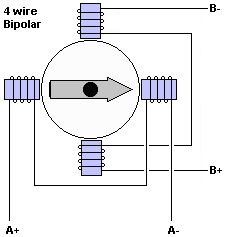
When you have all the "A" wires, pick up another unlabelled wire and label it "B" then repeat the spin test until you have all the "B" wires. 4 wire motors: Once you have the A and B sets, you can skip down to find the phases.
Repeat with C, D, and so on until you have all the wires in groups.
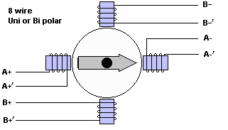
8 wire motors: If you only have two wires in each set and you have 4 sets (8 wires total) you can just pick one "A" wire, one "B" wire, one "C" wire and one "D" wire and hook them all together. This is now your common or M+ wire and the other wires are the phases. This wiring causes the motor to behave as a unipolar motor. It could also be wired together in a bipolar configuration if that were desired. (see Stepper Motor Connection Options for all the different ways you can hook your motor up) Some Bipolar drivers accept 8 leads, but many take 6 leads. In that case, one wire from each of two coils forms one common and one wire from each of the other two coils forms another common which results in the same wiring as a 6 wire motor. {ed: At this point, you know the wire sets, but not which wire is what phase. To complete your wiring, continue on with Bill Krause's 8 wire method below}
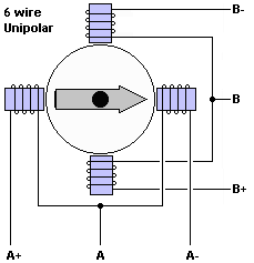
6 wire motors: If you have two sets of 3 wires (a 6 wire motor) you need to find the center wire of each set. Starting with the "A" set, label the wires A1, A2, and A3 in any order. Connect A1 to A2. Feel how hard it is to spin. Now connect that same A1 wire to the A3 wire in the set.
- If it is easier to spin, then the A2 wire is the center. Re-label A2 as "AC"- If it is harder to spin, then the A3 wire is the center. Re-label A3 as "AC"
- If it is the same, then the A1 wire is the center. Re-label A1 as "AC"
Repeat this for the B set to find the B center wire "BC"
Connect AC and BC together to form your common M+ wire. This modifies the motor to become a unipolar stepper. To use it in bipolar modes, keep AC and BC disconnected from each other any everything else (see Stepper Motor Connection Options for all the different ways you can hook your motor up) {ed: At this point, you know the wire sets and centers for each set, but not which wire is what phase. To complete your wiring, continue on with Bill Krause's 6 wire method below}
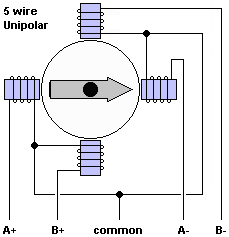
5 Wire Motors: If you have only one set of 5 wires then you have a standard unipolar motor. Connecting ANY two of the five wires together causes the shaft to be a little harder to turn. You might have noticed that one of the wires caused the motor to be harder to turn than the others. That was the center wire. If all the connections seemed about the same, the first wire you picked was probably the center.
Phases: Once you know which wire (s) is(are) the common, you can find the order of the phases with a stepper controller or a battery. If you can connect it to a controller and provide direction and step signals continuously, the motor will either turn, or shake. If it shakes, swap one of the A wires with one of the B wires. If it turns in the wrong direction, swap the two A wires. If your wires are labeled A, B, C, D rather than A+, A-, B+, B-, that should read: If the motor steps back and forth, swap B & C. If it runs backwards, swap A & B. {Thanks to Steve Baldmin or TLA Microsystems Ltd, Auckland, New Zealand}
With a battery, connect the common to one side, Then touch each wire to the other side of the battery until you find one that spins clockwise. Call this A. Pick another wire. If it goes clockwise too, call it B, and so on. If it doesn't, re-apply A, then pick another wire. Eventually you get A,B,C & D, and it should spin clockwise when voltage is applied in sequence. Reverse the sequence, and the motor should go backwards. {Ed:thanks to Tony Smith}
Stepper Motor Connection Options All the different ways you can hook your motor up, once you know which wire is what. Compares Unipolar, Bipolar Serial, Bipolar Parallel, Bipolar Single

 |

 |
+Phil Ritchey says:
[When I] hooked up the motor in SERIAL Bi-POLAR configuration I discovered: Once wired into two each 2 coils sets, shorting the ends of either of those sets together LOCKS the motor. But if you get the ends of a coil identified wrong (Backwards), the coil will NOT LOCK. A further test that you got it correct.
See also:
NEW! Roman Black's Linistep 1. stepper controller kit Proceeds support PICList.com
| file: /Techref/io/stepper/wiresbattery.htm, 7KB, , updated: 2021/3/16 18:24, local time: 2025/10/21 04:27,
216.73.216.53,10-2-207-162:LOG IN
|
| ©2025 These pages are served without commercial sponsorship. (No popup ads, etc...).Bandwidth abuse increases hosting cost forcing sponsorship or shutdown. This server aggressively defends against automated copying for any reason including offline viewing, duplication, etc... Please respect this requirement and DO NOT RIP THIS SITE. Questions? <A HREF="http://massmind.org/techref/io/stepper/wiresbattery.htm"> Stepper Motor wiring</A> |
| Did you find what you needed? |
Welcome to massmind.org! |
|
The Backwoods Guide to Computer Lingo |
.