Drilling holes in PCB's is not complex: put a drill bit in a drill press, position the drill where you want the hole and pull the lever slowly and gently until the drill passed through. If your artwork includes a small dot in the center of each pad, it will etch a hole though the copper which will serve to guide the bit to center if you allow the board to float slightly in your hands while making the initial contact.
A common problem is the drill bit ripping the anular ring off, destroying the pad but this can be avoided in several ways:
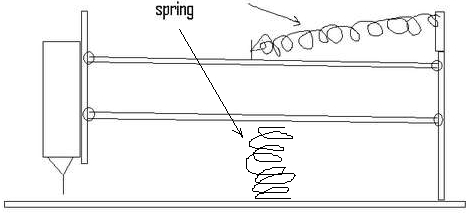
If you don't have a drill press, you can make a PCB drilling machine from a Dremel or other high speed rotary tool mounted vertically to a hinged piece of plywood or the like. As long as the hinge is a couple of feet back from the bit, the arc of the drill will not be significant. If you want to get fancy, use two hinged pieces in a parallelogram arrangement. A spring or two can help make the drill easy to lift.
The industry standard connecting between multiple layers for commercially made PCBs is plated through holes. There are a number of alternatives:
Dwayne Reid of Trinity Electronics Systems Ltd Edmonton, AB, CANADA says:
I have used the Multicore 'Coperset' system. They extrude solder in rods of the appropriate diameter and electroplate copper onto those rods. Then they score the copper at intervals somewhat more than 1/16th inches (longer than a PCB thickness). To use the system, you drill the holes EXACTLY the right diameter, place the board over an anvil and stick one of the rods into the hole. You break off a section by bending the rod back and forth so that you are left with a little cylinder sticking above the board. A sping-loaded punch is used to flatten that cyclinder - when you squash it length-wise, it gets fatter and the copper plating 'grips' the inside of the hole. Think of an old fashioned thermos bottle with the lever-type rubber stopper. Anyways, when you have done all the holes, you flood both sides of each loaction with solder, then heat up and remove the solder. Multicore suggests using solder-wick but I get better results with my vacuum desoldering system. Voila! Plated thru holes! Downsides: the orignal rods that I got weren't scored at the right distances (too short) and the little cylinders didn't grip the holes reliably. I understand that has been fixed. Also - its expensive and its time-consuming. But it does work.
You can save a lot of money by not buying the kit - only the rod refils. you can use an automatic pencil to dispense them.
Tony says:
What you could do is use a PC Board repair kit. They have small, metal, funnel shaped things that are hollow inside, actually like a real funnel:---------- \ / \ / | | | |You drop these into your thru holes. Then you take two pointy headed tools, and you press one into the top of the 'funnel' and one into the 'tube' end of the funnel. You expand the bottom of the tube and have a thing that looks like an empty thread spool thru your hole.
      -----------
     \           /
-----|          |---------
     |          |          PC Board
-----|          |-----------
     /           \
      -----------
We used them in the USAF to repair boards that a via or pad disintegrated due to heat.
Your local fabric store carries "sequin pins". These are small (0.018" diam by 1/2" long) pins with small heads. $3 or so for about 400. Drill a 0.022-0.024" hole, push the pin thru, and solder in place. Cut off the sharp end, and you've got a FAST, CHEAP, and EASY feedthru.+
Ted, KX4OM says:
These aren't rivets specifically designed for through-hole vias, but they work pretty well. They are 2mm in O.D. silver cylinders, .077" in length sold at Hobby Lobby for jewelry use here in the US. They are OK for the thinner sizes of double-sided boards. They are sold as crimp tubes, under the Westrim Crafts name. A bag of 62 is $1.49. They are very soft (I squished the one I measured with the digital caliper) and accept solder extremely well. A light touch with miniature Phillips screwdrivers applied simultaneously on both ends will flare their ends in the hole, keeping them in place until solder is applied.
Alan King says:
Don't forget you have another option, that may be viable since you described it as a lot of address/data lines. Old useless chips (or maybe even the blank test ones some places sell for soldering practice) make good via makers if you have a bit of flexibility in layout and can align your holes. Put them on .1" centers, bend the leads straight out from the chip so they'll be easier to cut, and solder in. Solder both sides and cut off the rest of the leads and chip. Is a heck of a lot faster than placing single wires by hand. Can use header etc what ever you have on hand, I just usually have junk chips. 50 is a bit much, but if you can lay it out so you have 2 rows of 20 and use an old 40 pin chip it can be managed..
Bertho says:
Regular eyelets are completely circular like a tube with a flared top and not suitable for PCB use. The correct type for PCB eyeletting are split lengthwise and not completely circular. The reason is that the circular one, like a funnel, solders to the bottom layer in a wave soldering machine and fills up with solder but there is not a capillary force to go over the edge and back under the eyelet top to properly solder the eyelet to the top side copper layer. With the split design solder wicks out and properly solders both sides.
Jeff Heiss says:
A friend descried to me a method for plating through holes. The plating is accomplished by inserting a wire into the hole and applying a high voltage to the wire, exploding it and connecting the layers together. A pdf (of the high voltage circuit) is available on google. https://docs.google.com/open?id=0B9UJMWQidYN0ZE1yNWEzQmluSWcCurt's description: It involves feeding a thin copper wire through the hole until it touches a massive ground plate which allows a capacitor charged to 300 - 400 volts to discharge and literally melt the wire rapidly enough to cause it to 'explode' and bond to the internal copper layers. I find that 10 to 15 bursts leave enough copper for a sturdy through hole. I use an X Y table to position the board under a chuck that grips the wire and is connected to the high voltage source. A small stepper motor feeds the wire through the chuck from a spool.
Other methods and thier limitations:
Also:
See also:
| file: /Techref/pcbholes.htm, 10KB, , updated: 2014/5/19 16:47, local time: 2025/10/19 16:06,
216.73.216.53,10-2-207-162:LOG IN
|
| ©2025 These pages are served without commercial sponsorship. (No popup ads, etc...).Bandwidth abuse increases hosting cost forcing sponsorship or shutdown. This server aggressively defends against automated copying for any reason including offline viewing, duplication, etc... Please respect this requirement and DO NOT RIP THIS SITE. Questions? <A HREF="http://massmind.org/techref/pcbholes.htm"> Printed Circuit Board, multicore copperset, drill, plating</A> |
| Did you find what you needed? |
Welcome to massmind.org! |
|
The Backwoods Guide to Computer Lingo |
.