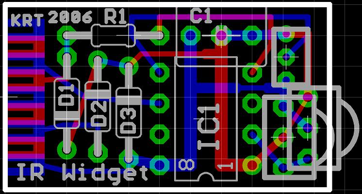
The IR Widget captures the infrared signals used by remote controls. It is able to determine the carrier frequency and demodulate the carrier in the digital or analog domain. The captured information can be used to reproduce or recognize the signal. The hardware is designed to be as simple and low cost as possible. A PIC12F629 was used for the prototype, but almost any PIC that uses the 12 or 14 bit instruction set could be used.
The usual approach to low cost IR capture typically consists of an IR detector or demodulator module connected to a serial or parallel port. This can work quite well when the CPU is dedicated to servicing the port. It does not work very well within a preemptive multitasking operating system. The OS is constantly servicing hardware interrupts even when the system is idle, so the IR capture is constantly interrupted. CPU usage is high when polling is used. Using the hardware interrupt capability of the port can greatly reduce CPU load, but interrupt latency may cause inaccurate results. Parallel and serial ports are becoming less common, and USB adapters do not work for these simple circuits.
The IR Widget solves these problems by using a microcontroller to do precise timing and send the data to the PC using ordinary asynchronous serial transmission. This allows the OS to service the serial port with it’s normal drivers and allows the use of USB to serial converters.
The circuit is powered from the serial port and the PIC directly drive the serial rx data line. An infrared detector module is used to allow the PIC to see every infrared pulse at close range. This allows for greatest detail and accuracy. An infrared demodulator module can also be used to allow for long range reception with less detail.
Infrared remotes typically use a carrier frequency of 30 to 60 kHz. The carrier is keyed full on and full off. Carrier on times typically range from 400 microseconds to several milliseconds. Carrier off times typically range from 400 microseconds to more than 100 milliseconds. To measure the frequency of a pulsed carrier, a short gate time is required. An ordinary frequency counter with 1 second gate will not give an accurate reading. The frequency could be determined from the period of one cycle, but this would require a rather high resolution measurement for a precise reading.
The IR Widget counts the number of infrared pulses that occur within a 100 microsecond period. The count is sent to the PC at 115200 bps. This repeats every 100 microseconds. To calculate the carrier frequency, the received data is scanned for the highest count. As long as there are pulses of 200 microseconds or greater duration, there will be samples from periods where the carrier was on for the entire sample period. These periods will have the highest count or one less than the highest count. The sum of all these periods is used to calculate the carrier frequency with reasonable precision. Once the carrier frequency is know, the periods with lesser counts can be evaluated to determine the duration of the carrier during those periods.
A Microsoft Windows program is used to transform the data gather from the IR Widget in to a graphical representation of the infrared signal. The display is similar to an oscilloscope or logic analyzer. The time of each carrier on and off period is shown as well as the count of pulses during the carrier on periods. Each capture is also written to a text file.
The infrared detector module for the previously described capture mode has a very short range. The remote must be within a few inches of the detector module. This is fine for research, but not suitable for remote control. Devices that are controlled by infrared remotes typically use an infrared demodulator modules. These modules are tuned to a specific carrier frequency and have a range of 20 feet or more. The IR Widget can accommodate such a module and has code for measuring the time between falling edges of the detector’s output.
The time it takes for an infrared demodulator module to respond to the presence and absence of the carrier is usually not the same and can very with the intensity of the infrared light. To allow for this asymmetry, the time of an on/off set is measured rather than discreetly measuring both the on time and off time. This will produce very consistent results with varying infrared intensity and various brands of IR demodulator modules.
The time between falling edges is measured with 64 microsecond resolution and sent to the host PC at 57600 bps upon every high to low transition of the detector.
A Microsoft Windows console program displays the count of 64 microseconds intervals, or optionally the actual time in microseconds.
See also: