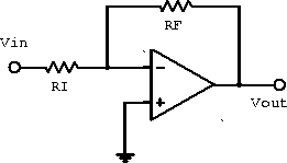
Figure 6.4: Inverting amplifier.
An inverting amplifier is shown in figure 6.4. Analysis of the circuit gives

Figure 6.4: Inverting amplifier.
![]()
Since ![]() (
( ![]() is at virtual ground),
is at virtual ground),
![]()
The gain is

The output is inverted with respect to the input signal.
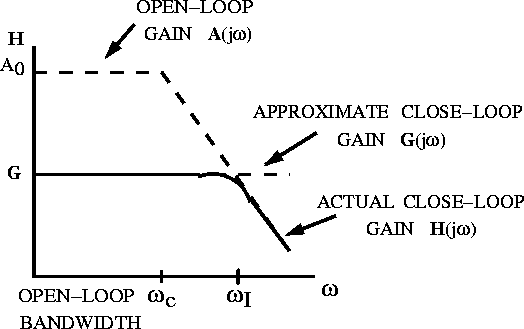
A sketch of the frequency response of the inverting and non-inverting amplifiers are shown in figure 6.5.

Figure 6.5: Inverting and non-inverting amplifier frequency
response.
The input impedance of the inverting amplifier is ![]() .
Since
.
Since ![]() we have
we have ![]() .
.
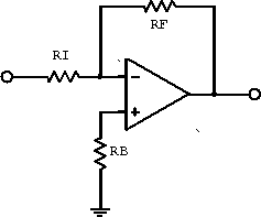
A better circuit for approximating an ideal inverting amplifier is shown in figure 6.6

Figure 6.6: Inverting amplifier with bias compensation.
The extra resistor is a current bias-compensation resistor. It reduces the current bias by eliminating non-zero current at the inputs.