An op-amp will in general have a small resistive output impedance from
the push-pull output stage.
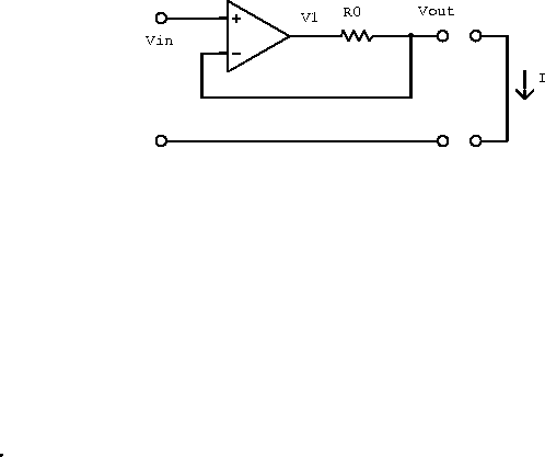
We will model the open-loop output impedance by adding a series resistor
![]() to the output of an ideal op-amp as shown in
figure 6.28.
to the output of an ideal op-amp as shown in
figure 6.28.

Figure 6.28: Real, current-limiting operational
amplifier partially modeled by an ideal amplifier and an output
resistor.
Assuming no current into the input terminals (unloaded), and hence no
current through ![]() , we have
, we have ![]() .
Using the open-loop transfer function
.
Using the open-loop transfer function ![]() we obtain
we obtain
![]()
Shorting a wire across the output gives ![]() and hence
and hence

Using the standard definition for the impedance gives
![]()
If ![]() than
than ![]() , which
is small as required by our infinite open-loop gain approximation.
, which
is small as required by our infinite open-loop gain approximation.
We can now draw the impedance outside the feedback loop and use
![]()
to obtain
![]()
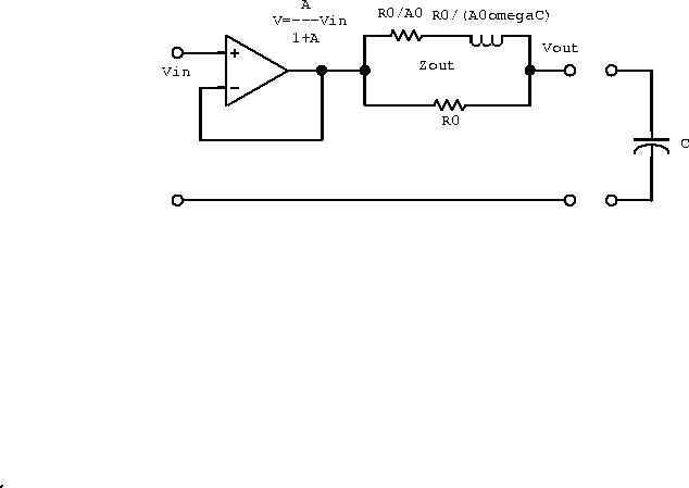
The circuit can now be modeled by a resistor ![]() in series with
an inductor
in series with
an inductor ![]() all in parallel with another resistor
all in parallel with another resistor
![]() (three passive components) as shown in figure 6.29.
Students should convince themselves of this.
(three passive components) as shown in figure 6.29.
Students should convince themselves of this.

Figure 6.29: An equivalent circuit for a 741-type operational
amplifier.
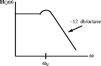
If the op-amp is used to drive a capacitive load, the inductive component in the output impedance could set up an LCR resonant circuit which would result in a slight peaking of the transfer function near the corner frequency as shown in figure 6.30

Figure 6.30: The overall transfer function when the amplifier
drives a capacitive load.