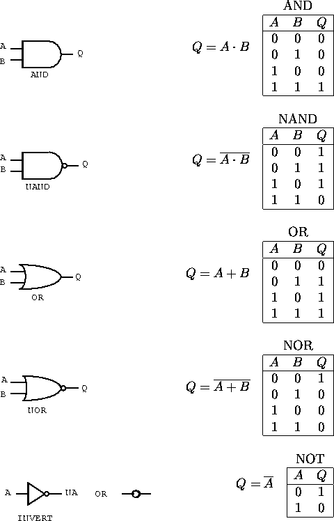
Figure 7.1: Symbols and truth tables for the four basic two-input gates: a) AND, b) NAND, c) OR, d) NOR and e) the inverter.
Electronic circuits which combine digital signals according to the Boolean algebra are referred to as logic gates; gates because they control the flow of information. Positive logic is an electronic representation in which the true state is at a higher voltage, while negative logic has the true state at a lower voltage. We will use the positive logic type in this course.
In digital circuits all inputs must be connected.
Logic circuits are grouped into families, each with their own set of detailed operating rules. Some common logic families are:
The ECL is very fast. The MOS features very low power consumption and hence is often used in LSI technology. The TTL is normally used for small-scale integrated circuit units.
The schematic symbols of the basic gates and the logic truth tables are shown in figure 7.1.

Figure 7.1: Symbols and truth tables for the four basic
two-input gates: a) AND, b) NAND, c) OR, d) NOR and e) the inverter.
The open circle is used to indicate the NOT or negation function and can be replaced by an inverter in any circuit. A signal is negated if it passes through the circle. Any logic operation can be formed from NAND or NOR gates or a combination of both. We also commonly have gates with more than two inputs. Inverter gates can be formed by applying the same logic signal to both inputs of an NOR or NAND gate.