The circuit shown in figure 5.8a is the basic common
emitter amplifier using the simplest biasing method.
Because it is constant, the power supply voltage ![]() is an AC
ground indistinguishable from the normal ground of the circuit.
We can therefore relocate the upper end of
is an AC
ground indistinguishable from the normal ground of the circuit.
We can therefore relocate the upper end of ![]() and
and ![]() to the
common ground line as shown in figure 5.8b.
The transistor symbol is ideal and
to the
common ground line as shown in figure 5.8b.
The transistor symbol is ideal and ![]() is shown explicitly as the
input impedance and hence
is shown explicitly as the
input impedance and hence ![]() .
.
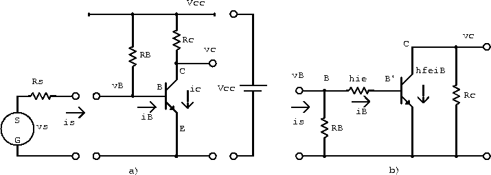
Figure 5.8: a) Basic CE amplifier and b) AC equivalent
circuit drawn using an ideal transistor symbol with ![]() shown
explicitly.
shown
explicitly.